
Just recently I was playing around with some moving platforms I had created for my game Shadow of the Orient. My game has horizontal and vertical moving platforms but it also has circular moving platforms as seen in the video below:
I wanted to add a visual aid to the radius of the circle which the platform follows along but i wasn’t quite sure how to do that – so I looked around on Google and found an article that explained how to work with the Line Renderer. After some messing around I was able to get my visual aid working quite nicely. The reason I wanted the visual aid was to give players a clue as to how much the platform needs to move before it comes into reach. So without further ado below is how i created my circular moving platform with the visual aid.
Setting up the structure
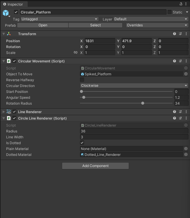
To set this up I first created a parent game object (Circular_Platform) which contains my main scripts for moving the platform along with the LineRenderer component to draw the visual aid. I then created my platform game object (Spiked_Platform) and added it as a child element of the parent game object as seen in the following reference:
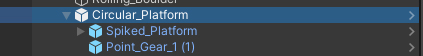
The Point_Gear_1 game object can be ignored for this tutorial – its the spinning gear i added to the center of the circle radius which rotates in the same direction as the moving platform.
Next I assigned the following two components to the “Circular_Platform” parent game object:
CircularMovement.cs
using UnityEngine;

public enum CircularDirection
{
    Clockwise,
    CounterClockwise
}

public class CircularMovement : MonoBehaviour
{
    [SerializeField] private GameObject objectToMove;
    [SerializeField] private bool reverseHalfway = false;
    [SerializeField] CircularDirection circularDirection = CircularDirection.Clockwise;
    [SerializeField, Range(0f, 20f)] private float startPosition = 0;
    [SerializeField, Range(0f, 50f)] private float angularSpeed = 1;
    [SerializeField, Range(0f, 50f)] private float rotationRadius = 20;

    //Internal vars
    private float _angle = 0f;
    private float _posX, _posY = 0f;
    private bool _flipDirection = false;
    private Vector2 _objecToMovePosition;
    private Transform _transform;

    private void Awake()
    {
        _transform = transform;
    }

    private void Start()
    {
        if(startPosition > 0)
        {
            //Set a starting point on the radius
            _posX = _transform.position.x + Mathf.Cos(startPosition) * rotationRadius;
            _posY = _transform.position.y + Mathf.Sin(startPosition) * rotationRadius;

            //Set the starting angle
            _angle = startPosition;

            //Assign the position to the moving object
            _objecToMovePosition.Set(_posX, _posY);
            objectToMove.transform.position = _objecToMovePosition;
        }
    }

    void Update()
    {
        Move();
    }

    private void Move()
    {
        //Check if the moving object should reverse course back to the starting point
        if (reverseHalfway)
        {
            if (Mathf.Abs(_angle) > 3.14)
                _flipDirection = true;
            else if (Mathf.Abs(_angle) <= 0.01f)
                _flipDirection = false;
        }

        //Check which direction to move
        if (circularDirection == CircularDirection.Clockwise)
            _angle = _flipDirection ? _angle + Time.deltaTime * angularSpeed : _angle - Time.deltaTime * angularSpeed;
        else
            _angle = _flipDirection ? _angle - Time.deltaTime * angularSpeed : _angle + Time.deltaTime * angularSpeed;

        //Calculate the angle of the x and y positions and include the rotation radius
        _posX = _transform.position.x + Mathf.Cos(_angle) * rotationRadius;
        _posY = _transform.position.y + Mathf.Sin(_angle) * rotationRadius;

        //Assign the movment to the object that needs to be moved
        _objecToMovePosition.Set(_posX, _posY);
        objectToMove.transform.position = _objecToMovePosition;
    }

#if UNITY_EDITOR
    private void OnDrawGizmosSelected()
    {
        Gizmos.color = Color.yellow;
        Gizmos.DrawWireSphere(transform.position, rotationRadius);

        Gizmos.color = Color.green;
        float _posX = transform.position.x + Mathf.Cos(_angle) * rotationRadius;
        float _posY = transform.position.y + Mathf.Sin(_angle) * rotationRadius;
        Gizmos.DrawCube(new Vector2(_posX, _posY), new Vector3(3, 3, 3));

    }
#endif

}
This code is responsible for moving the platform along a circular path and includes settings for speed, radius, starting position and a few more. I also added a visual gizmo so you can see the radius of the circle update in the unity editor as seen in the video below:
CircleLineRenderer.cs
The next component is a script I came across on Google and I’m sharing it here so you have a point of reference.
using UnityEngine;

[RequireComponent(typeof(LineRenderer))]
public class CircleLineRenderer : MonoBehaviour
{

    private const float DOTTED_LINE_TICKNESS_RATIO = 2.5f;
    private const int NUM_CAP_VERTICES = 6;

    [Tooltip("The radius of the circle perimeter")]
    public float radius = 2;

    [Tooltip("The width of the line for the circle perimeter")]
    public float lineWidth = 0.05f;

    [Tooltip("Check this to use the dotted line material for the circle perimeter line")]
    public bool isDotted = false;

    [Tooltip("The material for the plain line")]
    public Material plainMaterial;

    [Tooltip("The material for the dotted line")]
    public Material dottedMaterial;

    private LineRenderer lineRenderer;

    void Start()
    {
        lineRenderer = GetComponent<LineRenderer>();
        lineRenderer.useWorldSpace = false;
        lineRenderer.numCapVertices = NUM_CAP_VERTICES;
        SetRadius(radius);
    }

    void Update()
    {
        //While testing in-editor, refresh the circle each frame so we can test the circle by changing the fields in the inspector.
        if (Application.isEditor) SetRadius(radius);
    }

    //Call this method from other scripts to adjust the radius at runtime
    public void SetRadius(float pRadius)
    {
        radius = pRadius;

        if (radius <= 0.1f)
        {
            lineRenderer.positionCount = 0;
            return;
        }

        float tickness = lineWidth;
        if (isDotted) tickness *= DOTTED_LINE_TICKNESS_RATIO;
        lineRenderer.startWidth = tickness;
        lineRenderer.endWidth = tickness;

        //Calculate the number of vertices needed depending on radius so it always looks round.
        //For instance, huge circles need proportionaly less vertices than smaller ones to look good.
        //Source : http://stackoverflow.com/questions/11774038/how-to-render-a-circle-with-as-few-vertices-as-possible
        float e = 0.01f; //constant ratio to adjust, reduce this value for more vertices
        float th = Mathf.Acos(2 * Mathf.Pow(1 - e / radius, 2) - 1); //th is in radian
        int numberOfVertices = Mathf.CeilToInt(2 * Mathf.PI / th);

        lineRenderer.positionCount = numberOfVertices + 1;
        for (int i = 0; i < numberOfVertices + 1; i++)
        {
            float angle = (360f / (float)numberOfVertices) * (float)i;
            lineRenderer.SetPosition(i, radius * new Vector3(Mathf.Cos(Mathf.Deg2Rad * angle), Mathf.Sin(Mathf.Deg2Rad * angle), 0));
        }

        //Update material depending if its a dotted line or a plain one.
        if (isDotted)
        {
            lineRenderer.material = dottedMaterial;
            lineRenderer.materials[0].mainTextureScale = new Vector3(2 * Mathf.PI * radius * (1 / tickness), 1, 1);
        }
        else
        {
            lineRenderer.material = plainMaterial;
            lineRenderer.materials[0].mainTextureScale = Vector3.one;
        }
    }

    //Call this method from other scripts to adjust the width of the line at runtime
    public void SetWidth(float pWidth)
    {
        lineWidth = pWidth;
        SetRadius(radius);
    }

    //Call this method from other scripts to switch between plain and dotted line at runtime
    public void SetIsDotted(bool pIsDotted)
    {
        if (isDotted != pIsDotted)
        {
            isDotted = pIsDotted;
            SetRadius(radius);
        }
    }
}
This script creates the visual aid for my platform using the LineRenderer component. In order for this to work correctly you will need to create a material to get your visual aid to display in the game engine – in the image below you can see that I have the “Is Dotted” parameter checked on and i assigned a material called “Dotted_Line_Renderer” to the “Dotted Material” parameter.
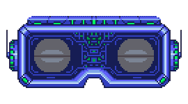
The following image shows the material which i created:
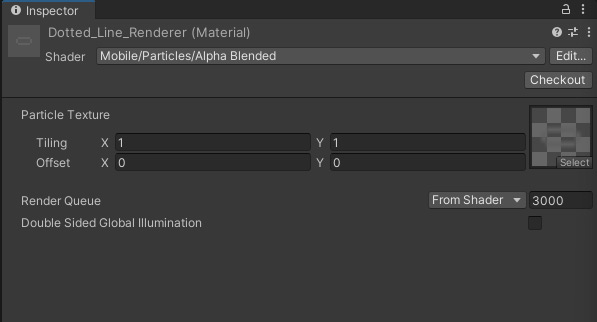
It’s to important to note that the tiling needs to be set to 1,1 and below is the graphic which I assigned to the material slot:
![]()
And that’s about it in a nutshell. To be honest i had never used the LineRenderer component and only became aware of it because ChatGPT recommended using it for drawing a repeating pattern along a line in Unity…yup ChatGPT…the A.I. modeling language that’s going to change the world in a big, big way.
Have questions? Feel free to post them below in the comments section.